What is 232\485\422 Communication? Common problems of Serial Communication

RS-232, RS-422, RS-485: What Are the Differences?
| Topics covered in this article: |
| Ⅰ. What is serial communication? |
| Ⅱ. What's the difference between the 232\485\422 communication? |
| Ⅲ. Frequently asked questions about serial communication |
Ⅰ. What is serial communication?
Only one line of data is transmitted at a time, and only one bit can be transmitted at a time using serial communication. One byte must be transmitted eight times in order to be received. Serial communication refers to the transmission of data strings via a single wire, which is why it's called a serial port.
In the event of low-rate requirements, sending data over a single line is extremely convenient and practical.
The asynchronous serial communication requires the format indicated below in order to send and receive proper data in a normal manner.

Figure. 1
There are various parameters in the serial port's communication parameters, including baud rate, start bit, data bit, parity bit, and stop bit.
Ⅱ. What's the difference between the 232\485\422 communication?
Serial communication is mainly divided into 232, 485, 422 three communication methods, what is the difference between these three?
01 232 Communications
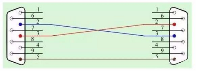
Figure. 2
RX, TX, and GND are the three lines that make up 232 communication. TX is linked to RX, RX is linked to TX, and GND is linked to GND, In this case, transmitting and receiving are handled by separate lines, allowing data to be transferred and received at the same time, a technique known as full-duplex communication.
To elaborate on this, full-featured serial communication, also known as a standard serial port, is another function of serial communication. Some devices process data faster than others due to data flow between two devices. Several control pins were added on the basis of RX and TX to assure normal data transfer, and finally, 9 pins were added, which is the common DB9, as shown in the diagram below.

Figure. 3
Many controllers, human-machine interfaces, PLCs, and other devices nowadays do not use traditional serial ports for serial communication, instead of using three lines of RX, TX, and GND.
02 485 communication
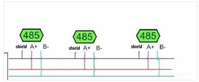
Figure. 4
485 was created to address the issue of 232's short communication distance.
The + and - two lines, often known as A and B lines, are all that are required for 485 communication. As data signals, the differential level signals of the two lines A and B are conveyed. Because these two lines are utilized for both sending and receiving, they can only be used for one of these functions at a time. As a result, 485 is a half-duplex mode of communication.
This is how the efficiency of 232 full-duplex is sacrificed in order to accomplish the expense of its great transmission distance.
03 422 Communications
The appearance of 422 is to realize the full-duplex communication method of 232 while also increasing the transmission distance to 485. The 422 is also known as 485-4, whilst the 485 is known as 485-2. The following diagram is a schematic illustration of 422 because 485-2 is two lines and 485-4 is four lines.
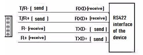
Figure. 5
422 is the result of dividing 232's RX into two lines, RX+ and RX-, and TX into TX+ and TX-. This allows you to send and receive data at the same time, as well as have a longer transmission distance of up to 485. However, such a beneficial communication strategy is rarely used. 232 and 485 are the most regularly utilized.
Ⅲ. Frequently asked questions about serial communication
1. The computer can communicate with the device using the USB to a serial port, but it cannot communicate with the device if it is replaced by the screen?
1) It's possible that the computer's USB to the serial port is linked to the device using the conventional serial port function, which means that other pins are used in addition to RX, TX, and GDN. Some pins on Omron and Mitsubishi PLCs, for example, must be short-circuited in order to communicate with the screen.
2) The computer scans the baud rate parameters while communicating with the controller or PLC, and adaptive screen communication may have fewer parameters than the equipment. There is a procedure for altering the baud rate for communication interaction in PLCs such as Mitsubishi and Keyence.
3) Another possibility is that the wiring method used is improper. Because male and female headers are required on some DB9s. There will be locations where TX is connected to TX and RX is connected to RX if you don't pay attention, so pay attention.
4) It should be noted that some serial helpers may be utilized to send test data to the controller at times. Please remind me because the parity check on some serial helpers does not work.
2. The screen of home A can communicate with the device, but the screen of home B cannot communicate?
1) Verify that the wiring is in order and that the RX and TX are compatible.
2) Check to see if the ground wire is connected.
3) Are there any more pins that need to be shorted in addition to RX, TX, and GND?
4) Whether the communication protocol is comprehensive or inconsistent, as well as the baud rate.
3. In the past, communication was possible without a ground wire. Why does a ground wire need to be changed for another device?
Because certain devices employ isolated power supply, this question is similar to the prior one. It used to be possible to communicate without grounding, but it's possible that the ground wire has been connected, allowing communication. It can be replaced with an isolated power supply, and because the grounds of the two devices are isolated, the ground wires on the serial port must be connected.
4. One device is 232, the other is 422, and there is no conversion device, what should I do?
Because these two are full-duplex, receiving and transmitting are divided, and 422 is only transmitted as a differential signal, I also mentioned the wiring of 422 and 232 just now.
Connect the RX+ of the 422 to the 232's TX, and the RX- of the 422 to the 232's GND,
Connect the TX+ of the 422 to the 232's RX, and the TX- of the 422 to the 232's GDN.
If the 422 device wants to convey data, it can do so by sending it to the 232's RX. Because TX and GND produce a differential signal to 422, 422 can receive data after the TX of 232 sends data.
5. No problem with 232 communication, no problem with 485 communication, after using 232 to 485, the communication is unstable?
The greatest distinction between 232 and 485 in terms of communication concept is the difference between full duplex and half duplex. The application layer, on the other hand, sends and receives data in either full-duplex or half-duplex mode.
However, 485 must be handled. Because it is half-duplex, it must be ensured that only sent or received data can pass via the path. The data will clash if both transmitting and receiving are enabled. As a result, the master station device, or the party that actively directs, must strictly manage the frequency with which data commands are sent. Of course, certain 232 to 485 devices are better, and this can be improved, but the master station must still control, and changing the communication rate is relatively sluggish.
6. What is the best way to achieve two screens or two master stations accessing Modbus devices through 485?
There is essentially one master and several slaves in 485 communication. Some clients, on the other hand, prefer to use two screens to access a Modbus device in practice. There is currently no viable option.
7. Weakness of serial communication?
1) When dealing with signal interference, it's best to utilize insulated cables and adhere to stringent wiring guidelines, such as grounding. Connecting a terminating resistor to match is also considered in some 485 communications. If the number is 232, keep the line short. Try to avoid data exchange of large messages in the communication protocol.
2) The baud rate matching issue Because the different crystal oscillators utilized produce inaccuracy in the computed baud rate of some devices, particularly controllers. As a result, at some baud speeds, such as 9600 baud, there is an error. What effect does the presence of errors have? Because the receiver performs a bit-by-bit calculation. If a message is too long, there will be an accumulation of errors, and the calculation will be skewed. As a result, there are some places where serial communication is unreliable, and care should be taken to prevent transmitting packets with very long data.
3) In some circumstances when there may be interference, you may want to consider utilizing odd parity or even parity since, while the likelihood of mistakes is low, if parity is added, at least erroneous packets can be filtered. Lose. It's as if there's no verification, and then the communication data is incorrect, and I'm not sure what to do. To avoid data errors, try using protocols with checksums.
4) Serial communication is inherently slow; therefore, please limit the data response requirements, as the serial transmission is slower than Ethernet. In addition, unlike a CPU, serial transmission is not multi-threaded. Even if you apply it to the software and how to utilize multi-threading to process the data, there is only one port at the bottom, and only one bit and one byte can be passed at a time since the data is sent out one port and one line. Because some customers communicate at a 9600 baud rate, how much data can be processed in how many milliseconds?
However, serial communication must be realistic, thus a thorough understanding of the protocol is beneficial to application development, testing, and communication.
8. Why not use synchronous communication?
As previously stated, synchronous communication is dependent on the clock signal. Who initiates this clock signal is a problem. A master device is frequently necessary to initiate a clock signal in synchronous communication in order to read the slave module's data. There are screen-reading PLCs and screen-reading data in practice. There is no master-slave relationship in asynchronous serial communication; both parties play equal roles and can transmit and receive data from each other. The CPU uses synchronous communication to read some modules, and the CPU begins the clock signal, such as reading the SD card module (which can be done via SPI ) and some sensor modules.
1. What is the difference between a 4-wire 485 serial port and a 2-wire 485 serial port?
The 4-wire 485 is full duplex, which can send and receive at the same time; The 2-wire 485 is half-duplex, and can only be sent or received at the same time. 4-wire 485 serial port is 422.
2. What is the difference between 232 serial port and 485 serial port?
1. The standard value of the maximum transmission distance of the rs-485 interface is 4000 feet, which can actually reach 3000 meters. In addition, the rs-232 interface only allows one transceiver to be connected to the bus, that is, single station capability.
2. The rs-485 interface allows up to 128 transceivers to be connected on the bus, with multi-station capability, so that users can easily establish a device network using a single rs-485 interface.
3. The rs232 interface signal level value is high, which is easy to damage the chip of the interface circuit, and because it is incompatible with the ttl level, it is necessary to use a level conversion circuit to connect with the ttl circuit.
3. What is the difference between synchronous 422 serial port and asynchronous 422 serial port?
Both the synchronous serial port and the asynchronous serial port are the embodiment of the RS232C mode. The main difference is in their transmission mode: asynchronous transmission refers to the transmission of data of one character (5~8 bits) at a time. Each character is preceded by a start bit and terminated by a stop bit. This enables the receiver to analyze the sender's data. But it is prone to timing drift.
And synchronous transmission is to use character-oriented or bit-oriented insertion method to control the start of a transmitted frame.
This is the difference between synchronous transmission and asynchronous transmission, and also the difference between the so-called synchronous serial port and asynchronous serial port.
The same is true for synchronous and asynchronous message transmission.
All of their differences are to allow the receiver to read the data sent by the sender.
 Discovering New and Advanced Methodology for Determining the Dynamic Characterization of Wide Bandgap DevicesSaumitra Jagdale15 March 20242344
For a long era, silicon has stood out as the primary material for fabricating electronic devices due to its affordability, moderate efficiency, and performance capabilities. Despite its widespread use, silicon faces several limitations that render it unsuitable for applications involving high power and elevated temperatures. As technological advancements continue and the industry demands enhanced efficiency from devices, these limitations become increasingly vivid. In the quest for electronic devices that are more potent, efficient, and compact, wide bandgap materials are emerging as a dominant player. Their superiority over silicon in crucial aspects such as efficiency, higher junction temperatures, power density, thinner drift regions, and faster switching speeds positions them as the preferred materials for the future of power electronics.
Read More A Comprehensive Guide to FPGA Development BoardsUTMEL11 September 20257937
This comprehensive guide will take you on a journey through the fascinating world of FPGA development boards. We’ll explore what they are, how they differ from microcontrollers, and most importantly, how to choose the perfect board for your needs. Whether you’re a seasoned engineer or a curious hobbyist, prepare to unlock new possibilities in hardware design and accelerate your projects. We’ll cover everything from budget-friendly options to specialized boards for image processing, delve into popular learning paths, and even provide insights into essential software like Vivado. By the end of this article, you’ll have a clear roadmap to navigate the FPGA landscape and make informed decisions for your next groundbreaking endeavor.
Read More Applications of FPGAs in Artificial Intelligence: A Comprehensive GuideUTMEL29 August 20252195
This comprehensive guide explores FPGAs as powerful AI accelerators that offer distinct advantages over traditional GPUs and CPUs. FPGAs provide reconfigurable hardware that can be customized for specific AI workloads, delivering superior energy efficiency, ultra-low latency, and deterministic performance—particularly valuable for edge AI applications. While GPUs excel at parallel processing for training, FPGAs shine in inference tasks through their adaptability and power optimization. The document covers practical implementation challenges, including development complexity and resource constraints, while highlighting solutions like High-Level Synthesis tools and vendor-specific AI development suites from Intel and AMD/Xilinx. Real-world applications span telecommunications, healthcare, autonomous vehicles, and financial services, demonstrating FPGAs' versatility in mission-critical systems requiring real-time processing and minimal power consumption.
Read More 800G Optical Transceivers: The Guide for AI Data CentersUTMEL24 December 20251024
The complete guide to 800G Optical Transceiver standards (QSFP-DD vs. OSFP). Overcome supply shortages and scale your AI data center with Utmel Electronic.
Read More Xilinx FPGAs: From Getting Started to Advanced Application DevelopmentUTMEL09 September 20252876
This guide is your comprehensive roadmap to understanding and mastering the world of Xilinx FPGA technology. From selecting your first board to deploying advanced AI applications, we'll cover everything you need to know to unlock the potential of these remarkable devices. The global FPGA market is on a significant growth trajectory, expected to expand from USD 8.37 billion in 2025 to USD 17.53 billion by 2035. This surge is fueled by the relentless demand for high-performance, adaptable computing in everything from 5G networks and data centers to autonomous vehicles and the Internet of Things (IoT). This guide will walk you through the key concepts, tools, and products in the Xilinx ecosystem, ensuring you're well-equipped to be a part of this technological revolution.
Read More
Subscribe to Utmel !
![AT88SC25616C-PU]() AT88SC25616C-PU
AT88SC25616C-PUMicrochip Technology
![FM3164-G]() FM3164-G
FM3164-GCypress Semiconductor Corp
![HCS301-I/P]() HCS301-I/P
HCS301-I/PMicrochip Technology
![L9660TR]() L9660TR
L9660TRSTMicroelectronics
![MOC3062VM]() MOC3062VM
MOC3062VMON Semiconductor
![MOC3020SR2M]() MOC3020SR2M
MOC3020SR2MON Semiconductor
![FGBS3040E1-F085]() FGBS3040E1-F085
FGBS3040E1-F085ON Semiconductor
![ATSHA204-TSU-T]() ATSHA204-TSU-T
ATSHA204-TSU-TMicrochip Technology
![AD8196ACPZ]() AD8196ACPZ
AD8196ACPZAnalog Devices Inc.
![TLE8110EDXUMA1]() TLE8110EDXUMA1
TLE8110EDXUMA1Infineon Technologies


